In electricity supply systems, an earthing system or grounding system is circuitry which connects parts of the electric circuit with the ground, thus defining the electric potentialof the conductors relative
to the Earth's conductive surface. The choice of earthing system can affect
the safety and electromagnetic compatibility of the power supply. In particular, it affects the magnitude and distribution of short circuit currents through the system, and the effects it creates on equipment and people in the proximity of the circuit. If a fault within an electrical device connects a live supply conductor to an exposed conductive surface, anyone touching it while electrically connected to the earth will complete a circuit back to the earthed supply conductor and receive an electric shock.
Regulations for earthing system vary considerably among countries and among different parts of electric systems. Most low voltage systems connect one supply conductor to the earth (ground).
A protective earth (PE), known as an equipment grounding conductor in the US National Electrical Code, avoids this hazard by keeping the exposed conductive surfaces of a device at earth potential. To avoid possible voltage drop no current is allowed to flow in this conductor under normal circumstances. In the event of a fault, currents will flow that should trip or blow the fuse or circuit breaker protecting the circuit. A high impedance line-to-ground fault insufficient to trip the overcurrent protection may still trip a residual-current device (ground fault circuit interrupter or GFCI in North America) if one is present. This disconnection in the event of a dangerous condition before someone receives a shock, is a fundamental tenet of modern wiring practice and in many documents is referred to as automatic disconnection of supply (ADS). The alternative is defence in depth, where multiple independent failures must occur to expose a dangerous condition - reinforced or double insulation come into this latter category.
In contrast, a functional earth connection serves a purpose other than shock protection, and may normally carry current. The most important example of a functional earth is theneutral in an electrical supply system. It is a current-carrying conductor connected to earth, often, but not always, at only one point to avoid flow of currents through the earth. The NEC calls it a groundED supply conductor to distinguish it from the equipment groundING conductor. Other examples of devices that use functional earth connections includesurge suppressors and electromagnetic interference filters, certain antennas and measurement instruments.
People use an earthing system mainly for these applications:
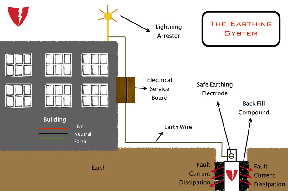
- To protect a structure from lightning strike, directing the lightning through the earthing system and into the ground rod rather than passing through the structure.
- Part of the safety system of mains electricity, preventing problems associated with floating ground and sky voltage.
- The most common ground plane for large monopole antenna and some other kinds of radio antenna.
Other, less common applications of earthing systems include:
- single-wire earth return.
- part of a system that powers small devices from sky voltage.
- one at each end of a ground dipole ELF antenna.

The conductor that connects the exposed metallic parts of the consumer's electrical installation is called protective earth (PE; see also: Ground). The conductor that connects to the star point in a three-phase system, or that carries the return current in a single-phase system, is called neutral (N). Three variants of TN systems are distinguished:
- TN−S
- PE and N are separate conductors that are connected together only near the power source. This arrangement is a current standard for most residential and industrial electric systems particularly in Europe.[citation needed]
- TN−C
- A combined PEN conductor fulfils the functions of both a PE and an N conductor.
- TN−C−S
- Part of the system uses a combined PEN conductor, which is at some point split up into separate PE and N lines. The combined PEN conductor typically occurs between the substation and the entry point into the building, and separated in the service head. In the UK, this system is also known as protective multiple earthing (PME), because of the practice of connecting the combined neutral-and-earth conductor to real earth at many locations, to reduce the risk of electric shock in the event of a broken PEN conductor - with a similar system in Australia and New Zealand being designated as multiple earthed neutral (MEN).


