Important Terms and Definitions related to Motor Control and Protection
2. Interrupting Medium:
(i) Air
(ii) Oil
(iii) SF6 gas
(iv) Vacuum
Abnormal Operating Condition and Causes of Induction Motors
3. Rated values of voltages:
(i) Rated voltage (Operational voltage)
For a three phase contactors, the voltage between phases is called rated voltage or operational voltage. (ii) Rated Insulation Voltage The voltage, on which performs the dielectric test.
The Star-Delta (Y-Δ) 3-phase Motor Starting Method by Automatic star-delta starter with Timer.
4. Rated Values of Current:
(i) Rated Thermal Current
The maximum current, on which a Contactor operates continuously for eight (8) hours without increasing the temperature (increased with a permissible limit).
(ii) Rated Operational Current
A Manufacturer tells the rated operational current considering Contactor’s rated frequency, operational voltages, rated duty and utilization factor.
Main Difference between contactor and Starter.
5. Rated duty and Serves Conditions:
(i) Eight Hours Duty
A Contactor can carry the normal current for more than 8 hours. The contactor’s rated thermal current can be found by 8 hours duty.
(ii) Uninterrupted duty
A Contactor can be close for a long time (from 8 hours to many years) without interruption. However, Due to Oxidation and dust on contacts, Temperature may be increased.
(iii) Contactor’s making Capacity
Contactor’s rated making capacity is the value of current, on which the contacts of contactor can make the connections (i.e. Contactor can close their contacts) without arcing or melting. A.C contactor’s making capacity is defined according to the Current Symmetrical Component’s R.M.S value.
(iv) Contactor’s Breaking Capacity
Contactor’s rated breaking capacity is the value of current, on which the contacts of contactor can break the connections (i.e. Contactor can open their contacts) without arcing or melting. A.C contactor’s breaking capacity is defined according to the Current R.M.S value.
Air Circuit Breaker (ACB): Construction, Operation, Types and Applications
Circuit Breaker
A circuit breaker is a device, which can
Make or Break a circuit manually or by remote control under normal conditions
Break a Circuit automatically under fault conditions (like over current, Short circuit, etc.)
Make a circuit manually or by remote control under fault conditions
A circuit breaker is used for switching mechanism and protection of the system. Other associated devises and components are also used for this purpose associated with circuit breakers like fuses, relays, switches etc. Circuit breakers are widely used in industries as well as Power system for controlling and protection of different parts of the circuit like switchgears, Transformers, Motors, Generators/Alternator etc., which leads the system stable and reliable.
There are different types of circuit breakers available in the market and we will discuss one by one in detail.
Air Circuit Breaker:
The type of circuit breaker, which operates in air (where air-blast as an arc quenching medium) at atmospheric pressure, is known to be an Air Circuit Breaker. Air circuit breaker has completely replaced by oil circuit breaker. In different countries, still it is a preferable choice to use an Air circuit breaker up to 15KV because, there is no chance of oil fire like in oil circuit breaker.
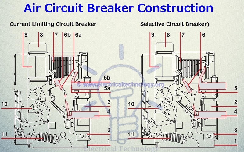
Construction of Air-Circuit Breaker
Air Circuit Breaker Construction (ABB EMax Low Voltage, Current Limiting Air Circuit Breaker and Selective (Non-Current Limiting) Air Circuit Breaker)
Delixi Air Circuit Breaker External labels (Rated Current and Voltage = 1kA, 415V)
OFF button (O)
ON button (I)
Main contact position indicator
Energy storage mechanism status indicator
Reset Button
LED Indicators
Controller
“Connection”, “Test” and “isolated” position stopper (the three-position latching/locking mechanism)
User-supplied padlock
Connection “,” Test “and” separation “of the position indication
Connection (CE) Separation, (CD) Test (CT) Position indication contacts
Rated Name Plate
Digital Displays
Mechanical energy storage handle
Shake (IN/OUT)
Rocker repository
Fault trip reset button
Internal Construction of Air Circuit Breaker (ABB EMax Low Voltage Current Limiting Air Circuit Breaker and Selective (Non-Current Limiting) Air Circuit Breaker)
(ABB EMax Low Voltage Current Limiting Air Circuit Breaker and Selective (Non-Current Limiting) Air Circuit Breaker)
1. Sheet Steel Supporting Structure
2. Current Transformer for Protection Trip Unit
3. Pole Group insulating box
4. Horizontal rare terminals
5a. Plates for fixed main contacts
5b. Plates for fixed arcing Contacts
6a. Plates for Main moving contacts
6b. Plates for Moving Arcing contacts
7. Arcing Chamber
8. Terminal box for fixed version – Sliding Contacts for withdrawable version
9. Protection Trip Unit
10. Circuit breaker Closing and Opening Control
11. Closing Springs
Principle of Operation of Air Circuit Breaker:
The working principle of Air Circuit breaker is rather different from other types of circuit breaker. The main aim of circuit breaker is to prevent reestablishment of arcing after current zero where the contact gap will withstand the system recovery voltage. It does it same work, but in a different manner. During interruption of arc, it creates an arc voltage instead of supply voltage. Arc voltage is defined as the minimum voltage required for maintaining arc .The circuit breaker increases the voltage in three different ways:
Arc voltage can be increased by cooling arc plasma. As soon as the temperature of arc plasma motion of particle in arc plasma is reduced, more voltage gradient will be required to maintain the arc.
By splitting the arc into a number of series will increases the arc voltage.
Arc voltage can be increased by lengthening the arc path. As soon length of arc path is increased the resistance path will increase more arc voltage is applied across the arc path hence arc voltage is increased.
It is operated within voltage level up to 1 KV. It contains two pairs of contact. The main pair carries the current and the contact made of copper. An additional pair of contact is made of carbon. When the breaker is opened, the main contact opens first. During opening of the main contact, the arc contact remains in touch with each other. The arcing gets initiated when arc contacts are separated. The circuit breaker is obsolete for medium voltage.
Types of Air circuit breaker:
Plain air circuit breaker or Cross-Blast Air Circuit Breaker
Air blast circuit breaker
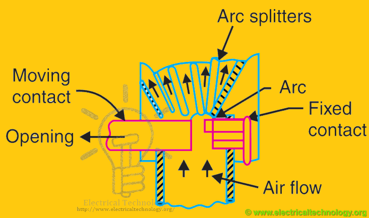
Plain air circuit breaker or Cross-Blast Air Circuit Breaker:
The circuit breaker is fitted with a chamber surrounding the contact. The chamber is known as “arc chute”. The arc is made to drive in it. The arc chute will help in achieving cooling. Arc chute is made from some refractory material. The inner walls of arc chute are shaped in such a way that arc is not only forced into close proximity, but will drive into the serpentine channel projected on arc chute wall.
The arc chute is divided into a number of small compartments by using metallic separation plates. Metallic separation plates are arc splitters and each of small compartments behave as a mini arc chute. Initial arc will split into a series of arcs this will make all arc voltages higher than system voltage. They are preferable choice in low voltage application.
Air blast circuit breaker:
This type of circuit breaker is used for system voltage of 245 KV, 420 KV and even more.
Air blast circuit breaker has further divided into three categories:
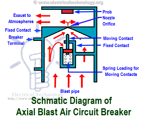
Axial blast breaker
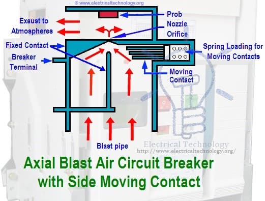
Axial blast with sliding moving contact.
Axial blast breaker:
The moving contact is in contact. There is a nozzle orifice in fixed contact at normal closed condition of breaker. When a fault occur high pressure is introduced into the chamber. High-pressure air will flow through nozzle orifice voltage is sufficient to sustain.
Axial blast with sliding moving contact:
The moving contact is fitted over a piston supported by a spring. The blast transfers arc to arcing electrode.
Advantages of Air-Blast Circuit Beaker
Air blast circuit breaker is a suitable option to use where frequent operation is required because of lesser arc energy
The risk of fire is eliminated in the operation of Air blast circuit breaker.
Air blast circuit breaker is small in size, because of the growth of dielectric strength is so rapid (which final contact gap needed for arc extinction is very small).
Speed of circuit breaker is much higher during operation of the air blast.
Arc quenching is much faster
The duration of the arc is same for all values of current.
Stability of operation can be maintained and depends on speed operation of circuit breakers.
It requires less maintenance.
Disadvantages of Air-Blast Circuit Breaker
The air supplier plant requires additional maintenance.
It contains high capacity air compressor.
There is a chance of air pressure leakage from the air pipes junction.
There is chance of a high rate rise of re-striking voltage and current chopping.
The air has relatively lower arc extinguishing properties.
Application and Uses of Air Circuit Breaker:
It is used for protection of plants
It is used for common protection of electrical machines
It used for protection of transformers, capacitors and generators.
Air circuit breaker is also used in Electricity sharing system and NGD about 15kV
Also used in Low as well as High voltage and Currents applications .
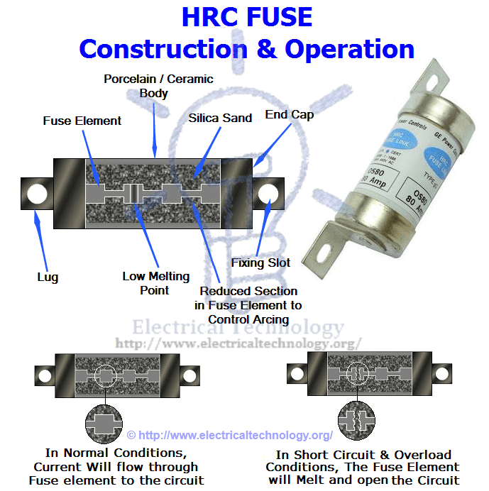
HRC Fuse (High Rupturing Capacity Fuse) and its Types
This type of fuse contains a fuse wire in it, which carries the short circuit current safely for a given time period. During this period, if fault is removed, then it does not blow off otherwise it will melt and remove the circuit from electrical supply hence, the circuit remains safe.
The common material, which is used to make an HRC fuse is glass, but this is not always the case. Other chemical compounds are also used in HRC fuse manufacturing and construction based on different factors. Its external enclosure is made fully airtight in order to avoid the effect of atmosphere on the fuse materials. The major objection on HRC fuse is low and uncertain breaking capacity of semi-enclosed fuse.
HRC Fuse (High Rupturing Capacity Fuse) and its Types
Construction and Operations of HRC fuse
HRC Fuse consists of highly heat resistant material (such as ceramic) body having metal-end caps, which is welded by silver current carrying element. The fuse body internal space is completely packed with a filling powder. The material, which has filled the insider space, may be plaster of Paris, quartz, chalk, marble, dust and cooling mediums etc. That’s why it carries normal current without overheating. The heat being produced vaporizes the silver melted element. Chemical reaction taking place between silver vapor and filling powder results in high resistance substance, which helps in quenching the arc in fuse.
HRC Fuse Construction and Operation
Advantages of HRC Fuse
It clears high as well as low fault currents.
Do not deteriorate with age.
Having high-speed operation.
Provides reliable discrimination.
Require no maintenance.
Cheaper than other circuit interrupting devices with same rating.
Permit consistent performance
Fusing operation is fast without Noise and Smoke
Disadvantages of H.R.C Fuse
After each operation, they have to be replaced.
Heat being produced by the arc may affect the associated switches.
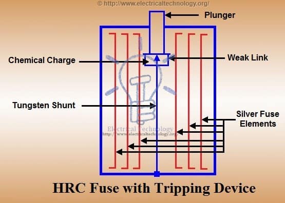
HRC Fuse with Tripping Device
When a fuse blows out the tripping device during the fault condition, it will cause the circuit breaker to operate. The body of fuse is made of ceramic material with a metallic cap fixed at each end. They are connected by series of silver fuse elements. There is a plunger at one end, which hits the tripping mechanism of circuit breaker under fault conditions, which leads it to operate the circuit. The plunger is connected through a fusible link and a tungsten wire to the other end of the cap.
HRC Fuse with tripping device
As fault occurs, the first element to be blown out is silver fuse and current is transferred to tungsten wire. The travel of the plunger is set such a way that is not ejected from the fuse body during fault conditions.
Advantages of HRC Fuse with Tripping Device:
During single-phase fault on a three-phase system, the plunger trips the circuit breaker, which opens all the three phases, i.e. it prevents single-phase supply as well.
The effects of the short circuit need to be considered in circuit breaker, which allow the use of an inexpensive circuit breaker.
The fuse-tripped breaker is capable of dealing with small currents, which avoids the necessity of replacing the fuse (except high current).
Low voltage H.R.C fuses are also available in a capacity of 16000A to 30,000A at 400V (Also available in range of 80kA to 120kA) . HRC Fuses are also used for protection on low voltage distribution systems against overload and short circuit conditions.
Types of HRC fuse:
NH Fuse
Din type
Blade contact
Types of HRC fuse
NH Type H.R.C Fuse:
NH fuse provides overload and short circuit protection for low and medium voltage. They provide backup protection to motor starters and other equipment against short circuit and overload. They are light in weight with compact dimension.
Din Type HRC Fuse:
Din type fuses are available in wide range of rated currents. DIN fuse are used for different purposes with their characteristic at different temperature condition. They types of fuses are available for different voltages level and can be used in transformer protection even where there is no LV (Low-Voltage) Secondary or backup protection. They have excellent clearing capability of ideal low over current with short-circuit performance. Other uses and application of DIN fuses are in air and gas insulated switchgear, mining, transformers and Feeder sectionalizing.
Blade Type HRC fuse:
This type of fuses (also known as spade or plug-in fuses) comes in plastic body and two metal caps to fit in the socket. Mostly, they used in automobiles for wiring and short circuit protection. They are light in weight. It contains low cutoff current. They are also used for short circuit and backup protection of motors. They are available in different sizes and shapes with different current rating capacity, which print on the top.
Application of H.R.C fuses:
Used for protection of Transformers, Motors and automobile, etc.
It is also used in motor stators
Backup protection
Few words:
After reviewing the advantages and disadvantages of H.R.C fuses for low voltage installation, which can be easily replaced. They provide high-speed operation in short circuit and over current protection. They also provide stability in industrial power distribution and semiconductor protection. Both fuse and circuit breaker complement each other in a low voltage system. They can be used to provide backup protection to the circuit breaker with high breaking capacity.
(Traffic Light Control Project Using IC 4017 Counter and Timer 555 )
Introduction
Traffic Lights are used to control the vehicular traffic. In the modern era, everyone has different types of vehicles resulting in rise to the numbers of vehicles. That’s why traffic lights are mandatory to avoid the traffic jams and accidents. There are three lights in the traffic signal, having different message for the drivers. Red light (upper one) asks the driver to yield at the intersection, green light (last one) gives the driver free license to drive through the intersection whereas the yellow light (middle one) alerts the driver to wait if the next light is red one or get ready to go / turn the engine ON if the green light is next.
Traffic light has proved to be an amazing way to stop the vehicular collisions and control the traffic jams in today’s modern era where everyone owns the different types of vehicles.
Project Proposal:
As we all know, the name of the project is “Traffic Light Control”. The fundamental idea of this simple electronic project is to control the traffic. It can be used to avoid the vehicular collisions and traffic jams. This project is just a one-way traffic controller, although it can be further modified as well. Project will work in a way, it provides the instruction to the driver whether to drive through the intersection or yield at the intersection.
Control Lights indication:
There are three control lights or signals, which will provide the instruction to the driver.
RED light – instructs the driver to STOP at the intersection.
YELLOW light – instructs the driver to WAIT (If red light is next) or GET READY (if green light is next)
GREEN light – instructs the driver to GO through the intersection.
Components Requirements:
There are quite a few components, which we will be using to make our Traffic LightControl System. Following is the list of the components.
9V Battery (Input Battery)
100K, 22K and 330 ohm resistors
1µF, 10µF and 2.2mF capacitors
Six 1N4148 diodes
555 timer IC (As a pulse generator)
4017 IC counter (Main IC of the circuit)
1M Potentiometer (Controls the timing of pulse generated by 555 timer)
Red, yellow and green LEDs. (Output)
Circuit Diagram of Traffic Light Control mini Project
Click image to enlarge
Working Principle:
This traffic light is made with the help of counter IC, which is mainly used for Sequential Circuits. We can also call it as Sequential Traffic Lights. Sequential Circuits are used to count the numbers in the series.
Coming to the working principle of Traffic Lights, the main IC is 4017 counter IC which is used to glow the Red, yellow and green LED respectively. 555 timer acts as a pulse generator providing an input to the 4017 counter IC. Timing of glow of certain lights totally depends upon the 555 timer’s pulse, which we can control via the Potentiometer so if you want to change the time of glow, you can do so by varying the potentiometer, having the responsibility for the timing. LEDs are not connected directly with 4017 counter, as the lights won’t be stable. We have used the combination of 1N4148 diodes and the LEDs in order to get the appropriate output. Main drawback of this circuit is that you can never have an exact timing with this, however you will have best estimated.
Phase or Line Tester is a tool which is used to identify or test the Phase/Live/Hot or Positive wire/Conductor.
Phase or Line Tester is also called Neon Screw Driver or Test Pin.
(Good to Know: Phase, Line, Hot, Live and Positive are the same terms)
Construction of Phase or Line Tester
Following are the main parts of a typical Phase or Line Tester.
1).Metallic Rod and Mouth
It is a cylindrical metal rod. The flat end (mouth) is used as a screw driver or touch electrical conductors/wires to find phase or live wires and the other end is connected to the resistance, neon bulb, element and metallic cap screw respectively. The flat end of cylindrical metal rod is also covered with transparent insulated plastic for insulation proposes except mouth.
2).Body and Insulation
All these components (Resistance, Neon bulb, Element or metallic spring, and Metallic Cap screw) are covered in a transparent insulated body which made of plastic. The flat end of cylindrical metal rod is also covered with transparent insulated plastic for insulation proposes except mouth.
3).Resistor
Resistor is an element which opposes the flow of current through it. In a Phase or Line Tester, Resistor is connected between cylindrical metal rod and Neon bulb to prevent high current and reduces it to a safe value for Neon bulb. Without a resistor, high current may damage the neon bulb. Moreover it would not be a safe to use this tool without resistor.
4).Neon Bulb
Neon bulb is connected between Resistance and Element (metallic spring). It is used as phase indicator bulb. When a small current flows through it, then it glows. Due to neon bulb, a Phase or Line tester is also called a Neon Screw driver.
5).Element (Metallic Spring)
Element (metallic spring) is used to make connection between neon bulb and metallic cap screw.
6).Metallic Cap Screw and Clip
Metallic Cap screw is used for tight all the components inside the Phase tester slot. In addition, Metallic cap screw is connected with spring (element) and spring (element) is connected with neon bulb. Moreover Clip is used for holding the phase tester in pocket.
Click image to enlarge
Click image to enlarge
Working of a Phase or Line Tester:
When we touch mouth (flat end of the Metallic rod) of Phase or Line tester with naked Live / hot wire whereas one of our finger touch the metallic Cap Screw or Clip of Phase/Line Tester, then circuit is completed and current start to flow in Metallic rod.
Metallic rod is connected to the resistor which reduces high current to a safe value. The reduced Current passes through Neon bulb which is connected to (metallic spring). Metallic spring is connected with metallic Cap screw which is in contact of our fingers. A very small current passes through our body to earth and complete the circuit. When circuit is completed, current starts to flow and the filament of neon bulb starts glowing. This indicates that the touched wire with Phase/Line Tester mouth is Phase/Line/Hot.
(Good to Know: Phase, Line, Hot, Live and Positive are the same terms)
If we perform the same action as mentioned above, and Neon bulb does not glow, it means that is a Neutral Wire/Conductor.
Click image to enlarge
Safety Precaution:
Never try to work on electricity without proper guidance and care
Work with electricity only in presence of those persons who has good knowledge and practical work to deal with electricity
Don’t touches the open wire/Conductor even tester shows absence of phase or hot supply
Use Line Tester only with 100V-500V
Don’t use Phase or Line Tester with High voltages
Don’t hit on the handle of Line tester otherwise, Neon bulb or element may damage.


")
")
")


