تعديل

الأحد، 19 أبريل 2015

How we do make Electricity ...Ac generator


Electricity is the set of physical phenomena associated with the presence and flow of electric charge 

Electricity gives a wide variety of well-known effects, such as lightning, static electricity, 

electromagnetic induction and electrical current. In addition, electricity permits the creation and 

.reception of electromagnetic radiation such as radio waves.


السبت، 18 أبريل 2015

Traffic Light Control Simple Electronic Project


Traffic Light Control Simple Electronic Project

(Traffic Light Control Project Using IC 4017 Counter and Timer 555 )

Introduction

Traffic Lights are used to control the vehicular traffic. In the modern era, everyone has different types of vehicles resulting in rise to the numbers of vehicles. That’s why traffic lights are mandatory to avoid the traffic jams and accidents. There are three lights in the traffic signal, having different message for the drivers. Red light (upper one) asks the driver to yield at the intersection, green light (last one) gives the driver free license to drive through the intersection whereas the yellow light (middle one) alerts the driver to wait if the next light is red one or get ready to go / turn the engine ON if the green light is next.
Traffic light has proved to be an amazing way to stop the vehicular collisions and control the traffic jams in today’s modern era where everyone owns the different types of vehicles.
Traffic Light Control Electronic Project using IC 4017 Counter & 555 Timer

Project Proposal:

As we all know, the name of the project is “Traffic Light Control”. The fundamental idea of this simple electronic project is to control the traffic. It can be used to avoid the vehicular collisions and traffic jams. This project is just a one-way traffic controller, although it can be further modified as well. Project will work in a way, it provides the instruction to the driver whether to drive through the intersection or yield at the intersection.

Control Lights indication:

There are three control lights or signals, which will provide the instruction to the driver.
  • RED light – instructs the driver to STOP at the intersection.
  • YELLOW light – instructs the driver to WAIT (If red light is next) or GET READY (if green light is next)
  • GREEN light – instructs the driver to GO through the intersection.

Components Requirements:

There are quite a few components, which we will be using to make our Traffic LightControl System. Following is the list of the components.
  1. 9V Battery (Input Battery)
  2. 100K, 22K and 330 ohm resistors
  3. 1µF, 10µF and 2.2mF capacitors
  4. Six 1N4148 diodes
  5. 555 timer IC (As a pulse generator)
  6. 4017 IC counter (Main IC of the circuit)
  7. 1M Potentiometer (Controls the timing of pulse generated by 555 timer)
  8. Red, yellow and green LEDs. (Output)

Circuit Diagram of Traffic Light Control  mini Project

Click image to enlarge
Traffic Light Control Electronic Project using IC 4017 Counter & 555 Timer

Working Principle:

This traffic light is made with the help of counter IC, which is mainly used for Sequential Circuits. We can also call it as Sequential Traffic Lights. Sequential Circuits are used to count the numbers in the series.
Coming to the working principle of Traffic Lights, the main IC is 4017 counter IC which is used to glow the Red, yellow and green LED respectively. 555 timer acts as a pulse generator providing an input to the 4017 counter IC. Timing of glow of certain lights totally depends upon the 555 timer’s pulse, which we can control via the Potentiometer so if you want to change the time of glow, you can do so by varying the potentiometer, having the responsibility for the timing. LEDs are not connected directly with 4017 counter, as the lights won’t be stable. We have used the combination of 1N4148 diodes and the LEDs in order to get the appropriate output. Main drawback of this circuit is that you can never have an exact timing with this, however you will have best estimated.

Phase or Line Tester


Phase or Line Tester

Phase or Line Tester is a tool which is used to identify or test the Phase/Live/Hot or Positive wire/Conductor.
Phase or Line Tester is also called Neon Screw Driver or Test Pin.
(Good to Know: Phase, Line, Hot, Live and Positive are the same terms)
 
Construction of Phase or Line Tester
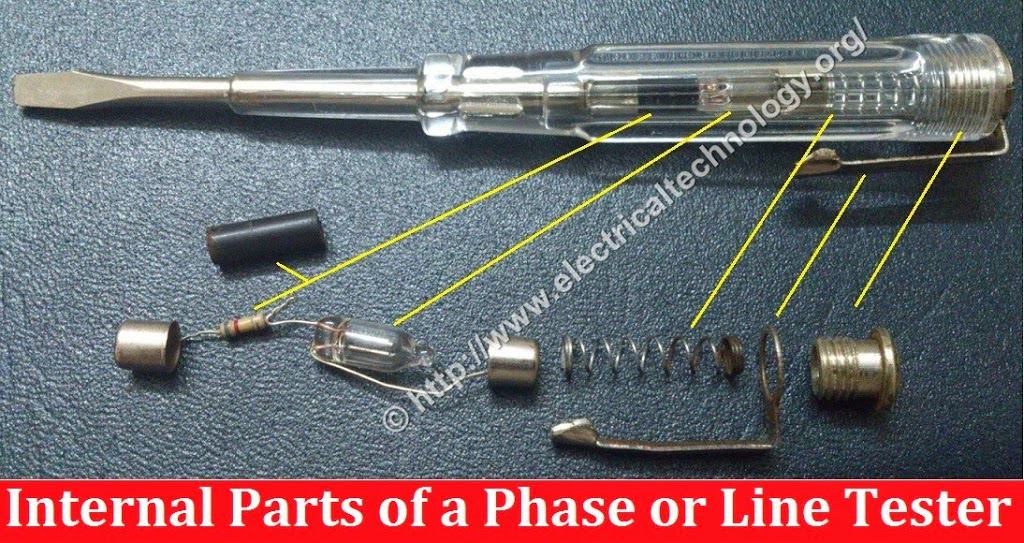
Following are the main parts of a typical Phase or Line Tester.
 
1).    Metallic Rod and Mouth
It is a cylindrical metal rod. The flat end (mouth) is used as a screw driver or touch electrical conductors/wires to find phase or live wires and the other end is connected to the resistance, neon bulb, element and metallic cap screw respectively. The flat end of cylindrical metal rod is also covered with transparent insulated plastic for insulation proposes except mouth.
 
2).   Body and Insulation
All these components (Resistance, Neon bulb, Element or metallic spring, and Metallic Cap screw) are covered in a transparent insulated body which made of plastic. The flat end of cylindrical metal rod is also covered with transparent insulated plastic for insulation proposes except mouth.
 
3).   Resistor
Resistor is an element which opposes the flow of current through it. In a Phase or Line Tester, Resistor is connected between cylindrical metal rod and Neon bulb to prevent high current and reduces it to a safe value for Neon bulb. Without a resistor, high current may damage the neon bulb. Moreover it would not be a safe to use this tool without resistor. 
 
4).   Neon Bulb
Neon bulb is connected between Resistance and Element (metallic spring). It is used as phase indicator bulb. When a small current flows through it, then it glows. Due to neon bulb, a Phase or Line tester is also called a Neon Screw driver.
 
5).   Element (Metallic Spring)
Element (metallic spring) is used to make connection between neon bulb and metallic cap screw.
 
6).   Metallic Cap Screw and Clip
Metallic Cap screw is used for tight all the components inside the Phase tester slot. In addition, Metallic cap screw is connected with spring (element) and spring (element) is connected with neon bulb. Moreover Clip is used for holding the phase tester in pocket. 
                                                                  Click image to enlarge
 
Construction and Internal parts of Electric Phase / Line Tester
                                                                 Click image to enlarge
How does an Electric Phase or Line Tester Work?
Working of a Phase or Line Tester:
When we touch mouth (flat end of the Metallic rod) of Phase or Line tester with naked Live / hot wire whereas one of our finger touch the metallic Cap Screw or Clip of Phase/Line Tester, then circuit is completed and current start to flow in Metallic rod.
Metallic rod is connected to the resistor which reduces high current to a safe value. The reduced Current passes through Neon bulb which is connected to (metallic spring). Metallic spring is connected with metallic Cap screw which is in contact of our fingers. A very small current passes through our body to earth and complete the circuit. When circuit is completed, current starts to flow and the filament of neon bulb starts glowing. This indicates that the touched wire with Phase/Line Tester mouth is Phase/Line/Hot.
(Good to Know: Phase, Line, Hot, Live and Positive are the same terms)
If we perform the same action as mentioned above, and Neon bulb does not glow, it means that is a Neutral Wire/Conductor.                                                                 
                                                                 Click image to enlarge
 
How does an Electric Phase or Line Tester Work?
Safety Precaution:
  • Never try to work on electricity without proper guidance and care
  • Work with electricity only in presence of those persons who has good knowledge and practical work to deal with electricity
  • Don’t touches the open wire/Conductor even tester shows absence of phase or hot supply
  • Use Line Tester only with 100V-500V
  • Don’t use Phase or Line Tester with High voltages
  • Don’t hit on the handle of Line tester otherwise, Neon bulb or element may damage.

Ferrite Bead: Tiny Cylinder in Power Cords & Cable. Why


Ferrite Bead: Tiny Cylinder in Power Cords & Cable. Why

Have you ever noticed a little cylinder in a power cords and cable? Have you ever seen the same in your laptop charger cord, USB cord, Mobile charger cable cord, Printer Cord, Monitor cord, etc. even in Mouse and keyboard cable cords? Today, we are going to tell you the secret story behind it.
Ferrite Bead Tiny Cylinder in Power Cords & Cable. Why
Theoretically, this Tiny Cylinder in Power Cords & Cable is ferrite choke or ferrite bead as shown in the below image.
The ferrite choke is an object in the cylindrical shape, which made up of Ferrite material (which is a magnetic material). A typical Ferrite choke (e.g. Solenoid) consists of an insulated wire around a magnetic material. In our case, cable is insulator and ferrite cylinder is magnetic material to make a special kind of lump for the power cable and cords.
Tiny Cylinder in Power Cords & Cable. Ferrite choke and bead
Ferrite Bead (or Ferrite choke) playing a very important rule. As we know that, when current passes through the conductors (inside the power cords), it produces EMF (Electromotive Force) or Radio Energy. The power cords and cable transfer this energy outside in the form of noise, which disturb and interfere with other electronics devices such as nearby radio sound would be noisy with improper tuning of channel. In addition, some electrical energy is wasted in the form of radiation, which also reduces the supply power to the battery or other connected devices, which leads to increase the charging time of battery.
what is the tiny cylinder in power cords and cable usb printer charger
Ferrite Bead has the ability to stop and block the emission of radio waves form the power cords and uses electrical energy for charging purpose only without power losses. Due to this important factor, that’s why are there a tiny cylinder in your laptop or mobile charger cords. Now, I think it is enough because you have clear understanding of the purpose of this magical tiny object (ferrite bead or ferrite choke) in the cylindrical shape in power cords and cables.

Why Parallel Connection is Mostly Preferred over Series Connection?


Introduction to Series & Parallel Connections


The use, application and importance of series and parallel circuit connection today cannot be over emphasized. The application of series and parallel circuit connection can be evidently seen in our homes, school halls and in our street lights. With the press of a button, all the Bobs in our sitting rooms are turned on. some refer that the bobs in their homes should have different switches.
Introduction to Series & Parallel Connections
Well, it’s not a magic when more than three electric bobs or loads are controlled by one switch. A load is anything i.e. it could be an appliances, electric bobs or even ceiling fans that consumes electrical energy when connected to a power supply. The electric bobs, televisions, refrigerators etc can all be referred to as a load. The bobs convert electrical energy into light and heat form of energy. Fans convert the electrical energy into mechanical energy.
The type of connection done to our ceiling fans, electric bobs will determine if they will have a common switch or not. Series circuit connection gives us the opportunity to connect more than two loads to a common switch. Street lights are a very good example of this. Parallel circuit connection makes it possible for us to connect loads to their individual switch. Both series and parallel circuit connection are good but one is mostly preferred over the other for one reason or the other. Before we talk about the reason why parallel circuit connection is preferred over series connection, let’s recall what series and parallel connections are first.

SERIES CIRCUIT

A series circuit is a circuit in which resistors or loads are connected end to end so that the circuit will have only one path through which electric current flows. Thus, when a number of resistors are connected in series, the effective resistance (total resistance in the circuit) is gotten by adding the individual resistance algebraically. That is to say, if we have resistors with resistance R1, R2, R3 …Rn connected in series, then;
Reff = RT = R1 + R2 + R3 + …Rn.
In series connections, the same current flows across all the branches of the circuits, but different voltage across it thus making the resistors to have different voltage across them. Each resistor or load will experience a voltage drop. The applied voltage is equal to the sum of the voltage drop across the different parts of the circuit. Voltage drop is proportional to the resistance current being the same throughout the circuit. When loads are connected in series, the loads will tend to have a common switch. This kind of connection is employed in school halls, street lights.

Uses & Application of Series Connection

Some people connect security lights in their homes in series which will make them to have common switch. The problem with this kind of connection is that when a load develops a problem, the other connected system will fail. It’s an all or none type of circuit connection. Till a load gets energy before it delivers it to the other and the one to deliver fails, there will be a black out.
Series circuit connections are common and greatly employed in electrical equipments. The tube filaments in small radios are usually in series. Current controlling devices are always connected in series with the device that they protect. Fuses are connected in series with the device they protect, Automatic house-heating equipment has a thermostat, electromagnetic coils, and safety cut-outs connected in series with avoltage source etc.

PARALLEL CIRCUIT

Resistors, loads are said to be connected in parallel when the end of each of the resistors or loads have a common point or junction and the other ends are also connected to a common point or junction. Such circuits are known as parallel circuits.
Unlike the series circuit connection, when finding the total (effective) resistance in a parallel circuit, the reciprocal of the individual resistance is taken. Thus, when a number of resistances are connected in parallel, the reciprocal of the effective resistance is given by the arithmetic or algebraic sum of the reciprocal of the individual resistance.
1/Reff or 1/RT = 1/R1 + 1/R2 + 1/R3 …1/Rn.
Parallel circuit connection have the same voltage flowing across all the branches of the circuits. Different resistors have their individual currents.

Uses & Application of Parallel Connection

Parallel circuit connection is very common in use. Various lamps and electrical appliances in our homes are connected in parallel so that each of the lamps or bobs and appliances can be operated independently. For us to have control over the individual lamps or loads, they have to be wired in parallel.

ADVANTAGE OF PARALLEL CIRCUIT CONNECTION OVER SERIES CIRCUIT CONNECTION.

A series circuit connection is an all or none type of circuit connection. Meaning that if one of the appliances fails, all the other appliances will also fail which is why this type of connection is good only when we want to protect a device.
Advantage of parallel circuit connection over series circuit connection
When a fuse gets burnt for instance due to high current, then the appliance it protects will not be damaged because current will no longer reach it. While series connection is an all or none, parallel circuit connection gives you the opportunity to give the loads and the appliances their individual switch. Parallel connection offers resistance to the flow of current compared to series connection.

A 100 ohms and a 150 ohms resistors connected in parallel will have less effect on electric current compared to 50 ohms and 40 ohms resistors connected in series. In electronic devices, parallel connection is paramount. The cells in a power bank are all connected in parallel. Parallel connection makes electrical energy to last longer. The cells themselves have their internal resistance, so if they were connected in series, some of the energy will be lost overcoming the internal resistance since it’s effect is high when in series than when in parallel.

Nuclear Power. Why is It The Last Option in Most Countries?


INTRODUCTION

Nuclear energy is becoming well developed as a source of energy. Compared to other sources of energy like solar energy, and hydroelectricity, nuclear energy is more stable in that its power supply is stable. Power generated by hydroelectric power plant is always dependent on the volume of water in a dam. Likewise the energy generated by the solar panels depends on the amount of sun it receives.
While the amount of energy generated by hydroelectric power plant and solar panelsfluctuates, nuclear energy is not like that. The main raw material for nuclear energy is a radioactive element. The nucleus of a radioactive element is unstable in its ways. Its nucleus will keep on splitting spontaneously until it attains stability. During that process energy is released and such phenomenon is called radioactivity.
To understand better how the energy produced by a radioactive element is harnessed to give us electricity, let’s see how the radioactive elements produces the energy in their nucleus. Remember that the nucleus of these elements are never stable. They’ll keep on splitting until they attain stability, that’s if they can. The process will lead to the release of energy, emission of gamma ray, beta ray, and alpha particle.

NUCLEAR FISSION

Nuclear fission occurs when the nucleus of a radioactive element (Radium, Uranium) is bombarded with a stream of fast moving neutron. This process results in the splitting of a radioactive element into a relatively heavy nucleus which is accompanied by energy release.

NUCLEAR FUSION

While nuclear fission involves the bombardment of a heavy nucleus to give two relatively heavy nucleus, nuclear fusion releases energy when two lighter nucleus fuses together to form a heavier nucleus. Nuclear fusion results from bombardment of two lighter nucleus with fast moving neutrons.


NUCLEAR FISSION and Fussion


MATTER TO ENERGY CONVERSION EQUATION

A very careful measurement has shown that when it comes to nuclear changes, the laws of conservation of matter and energy do not hold even though they still are applicable in our everyday life and much of it is also seen in physics. During nuclear reaction, small amount of matter gets destroyed in the process.
That is irrelevant when it comes to chemical reaction however, when Radium which is a radioactive element decays radioactively, a fraction of it is lost in the process while energy is gained. It seems that matter is being converted into energy. This is absurd and hard to believe because we don’t see it happen in our everyday life or in our physics laboratory.
It was spoken of by Albert Einstein and later proved by measurements. Albert Einstein suggested that the conversion of matter into energy is given by:
E = ΔMc2   … (Δ pronounced as “Delta” means “change in”.
Where;
  • E = Energy
  • C = Speed of light in m/s
  • Delta (Δ) M is the matter lost during the process of the nuclear reaction.
according to this equation of energy, mass can be converted into energy and vise versa. in addition, the explosion of atomic bombs on Nagasaki and Hiroshima (Japan’s Cities) in 1945 (during world war II) were base upon this equation.

HOW ELECTRICAL ENERGY IS GENERATED USING NUCLEAR ENERGY?

The earlier types of nuclear power station generated electricity through the fission of Uranium – 235. A block of graphite ( carbon ) is placed at the core of the nuclear reactor to reduce or minimize the speed of the neutrons. The reason why the velocity of the neutrons have to be minimized is because only at a low velocity can the neutrons penetrate the nucleus of the Uranium – 235 atom. There are tabular channels passing through the graphite block.
HOW ELECTRICITY IS GENERATED FROM NUCLEAR ENERGY. Nuclear Power
The nuclear fuel (Uranium ) is placed in the channels in the graphite blocks. The Uranium is contained in an Aluminium tube. During the nuclear reaction, the graphite surrounding the Uranium makes sure that the neutrons entering the Uranium is at low or regulated velocity.

Among the Uranium rods are other rods, made of boron steel. The use of boron steel is to absorb excessive neutrons. By varying the number of the boron steel rods in the reactor, the speed of the reaction is also regulated.
For safety reason, the boron steel rods that are not fully lowered are held by electromagnetic catches. If the reaction is going too fast, the rods will be dropped quickly into the channels in the core to slow the reaction.
The energy emitted by the nuclear energy during reaction causes an increase in the internal energy and other materials in the reactor. In some designs of nuclear power plant, carbon dioxide (gas) is pumped through the channels in the core and is heated by the internal heat energy generated during the nuclear fission.
The hot gas is finally channeled out of the core to a heat exchanger where the hot gas is used to boil water. The steam produced while boiling the water is used to turn the turbine which is connected to electric generated. By this stages, nuclear fission is converted to electrical energy. The fuel used by the reactor described above is Uranium – 235 which is quite rare. A more advanced and a cheaper reactor recently developed is a reactor called Breeder Reactor.
It breed its own fuel. It make use of Uranium – 238 which is very common. The reaction requires fast moving neutrons to split the Uranium – 238 nuclei unlike the other reactor which requires slow moving neutrons. During the reaction, Uranium – 238 is converted to plutonium – 239. The breeder reactor is more economical. While CO2 was pumped into the reactor of the other type, liquid sodium ( Na ) is pumped into the breeder reactor.
The essence of CO2 and liquid Na, is to serve as cooling liquid, to cool the system by absorbing the heat energy of the system which in turn is used to boil water to generate steam for the turbine which turns the electric generator.

ADVANTAGE OF NUCLEAR ENERGY

Nuclear energy has advantage over the other sources of energy in that it generates more energy and is more stable. The amount of energy it generates is not dependent on the intensity of the sun or the volume of water a dam holds like the hydroelectric power plant. Also read. Very simple hydroelectric project

DISADVANTAGE OF NUCLEAR ENERGY

  • Disposal of nuclear  and radioactive waste is very expansive.
  • Risk of Nuclear Accidents
  • Problem of Nuclear Radiation
  • Shut down reactors for specific time
  • Costly maintenance
  • Non Renewable and Fuel Availability problems

WHY OTHER COUNTRIES THINK OF IT AS THE LAST OPTION?

It’s no no news that radioactive radiation is very dangerous. It causes cancer and so many other deadly disease. Worst of all, it causes genetic mutation. You don’t just get up and say you want to build a nuclear power plant, you have to consider one factor.
This one factor affects everything and is the primary reason why some countries think of it as the last option. It’s not the cost of the fuel..,,, Where is the nuclear waste going to be disposed?
This factor affects whatever choice that is to be made. Dispose it in the sea? People fish and more over that country isn’t the only country making use of the sea. Dispose it on land?
What about farmers and the people living around the area? The problem of disposal of nuclear waste is one of the reasons some countries take it as the last option.

Twitter Delicious Facebook Digg Stumbleupon Favorites More